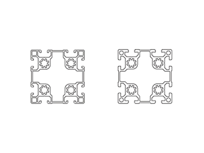
The Ultimate Guide to Custom Aluminum Extrusion Profiles
Have you ever examined the clean lines of contemporary architecture, the chassis of a premium mountain bike, or the mounting rails of a photovoltaic array and wondered about the manufacturing precision behind those metal forms? The answer lies in aluminum extrusion. However, when standard, off-the-shelf profiles fail to meet the specific geometric or functional requirements of your application, custom aluminum extrusion profiles become the engineering solution of choice.
Designing a custom profile is analogous to commissioning a tailored garment. While a ready-to-wear suit may suffice, a bespoke piece is meticulously contoured to your exact dimensions and intended function. This guide provides a technical exploration of custom extrusion, detailing the underlying processes and offering actionable insights for integrating this manufacturing method into your next high-performance project.
What Is Aluminum Extrusion? A Technical Overview
At its core, aluminum extrusion is a controlled, high-pressure deformation process used to produce linear components with a fixed cross-sectional profile. The process begins with a cylindrical billet of aluminum alloy, which is preheated to a temperature range typically between 400 °C and 500 °C—sufficiently high to render the material malleable but below its melting point. This heated billet is then mechanically forced, using a hydraulic ram, through a precision-engineered steel die. The die contains one or more openings that define the desired cross-sectional geometry.
As the aluminum exits the die, it acquires the exact shape of the opening, emerging as a continuous, elongated profile. This profile is subsequently cooled—often via air, water, or controlled quenching—then stretched to relieve residual stresses, and finally cut to specified lengths for further processing or finishing.
The intrinsic efficiency of aluminum extrusion lies in its ability to generate highly complex, thin-walled, or multi-void shapes that would be difficult or cost-prohibitive to achieve through alternative methods such as roll forming or machining. Furthermore, the resulting profiles combine the inherent advantages of aluminum alloy: a high strength-to-weight ratio, excellent corrosion resistance, thermal and electrical conductivity, and full recyclability. This makes the extrusion process particularly valuable for industries ranging from aerospace and automotive to consumer electronics and renewable energy infrastructure.
The Play-Doh Analogy: A Conceptual Model of the Extrusion Process
If you have ever used a Play-Doh Fun Factory as a child, you already possess an intuitive understanding of the fundamental mechanics of extrusion. Consider the process: a soft, pliable clay is loaded into a cylindrical chamber, after which a lever or plunger is depressed, forcing the material through a perforated die plate. The result is a continuous strand of clay—often star-shaped, spaghetti-like, or otherwise geometrically defined—that emerges from the opening.
Aluminum extrusion operates on precisely the same principle, albeit at an industrial scale and under vastly more demanding conditions. Where the Play-Doh process uses hand pressure and room-temperature clay, aluminum extrusion employs hydraulic rams capable of generating hundreds to thousands of tons of force. The “clay” is instead a preheated aluminum billet at approximately 400–500 °C (750–930 °F) —hot enough to be malleable, yet still solid. The “Fun Factory” becomes a high-strength steel die, precision-machined to tolerances measured in hundredths of a millimeter. And the gentle squeeze of a child’s hand is replaced by the controlled, relentless power of a hydraulic press.
The analogy is more than merely illustrative; it accurately reflects the core physical principle: a material is constrained within a container and forced under pressure to flow through a shaped opening, taking on that opening’s cross-sectional form as it exits. Once the analogy is understood, the leap from Play-Doh to practice is straightforward—only the temperatures, pressures, and materials have changed.
Why Choose Custom Over Standard Profiles?
Standard extruded profiles—such as solid bars, rectangular tubes, and equal or unequal angles—offer convenience and wide availability. However, they rarely align perfectly with the geometric and functional requirements of a specific application. Incorporating a standard profile into a custom assembly typically necessitates secondary operations: cutting, drilling, milling, bending, welding, or mechanical fastening. Each additional step introduces tolerance stack-ups, potential stress risers, increased labor costs, and longer production lead times.
Custom aluminum extrusion profiles are engineered to eliminate these inefficiencies at the source. By designing a profile tailored to your exact application, you can integrate functional features directly into the cross-section—features that would otherwise require post‑extrusion fabrication. Common examples include:
- Snap‑fit joints for tool‑free assembly
- Screw bosses and threaded channels for secure fastening
- Interlocking tracks or tongue‑and‑groove geometries for modular connections
- Integrated cooling fins for thermal management
- Cable management slots or hollow voids for routing wires or reducing weight
The benefits extend beyond geometry. A well‑designed custom profile reduces material waste, because every gram of aluminum serves a structural or functional purpose. It improves structural integrity, since load paths can be optimized and discontinuities (such as weld joints) are avoided. And crucially, it compresses the production timeline by consolidating multiple fabrication steps into a single extrusion pass.
In short, custom profiles transform the extruded shape from a semi‑finished commodity into a precision-engineered component—ready for use with minimal downstream processing.
Key Application Areas of Custom Aluminum Profiles
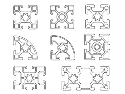
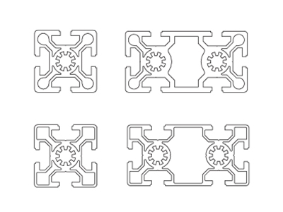
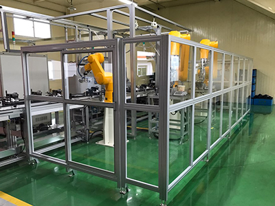
Custom aluminum extrusion profiles are utilized across a wide range of industries due to their excellent strength-to-weight ratio, corrosion resistance, thermal conductivity, and design flexibility. The primary application areas include:
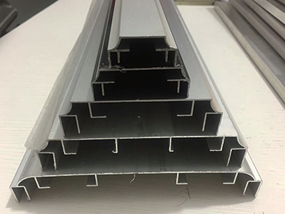
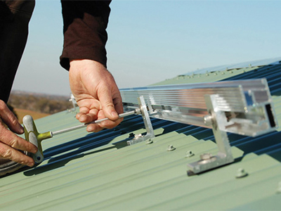
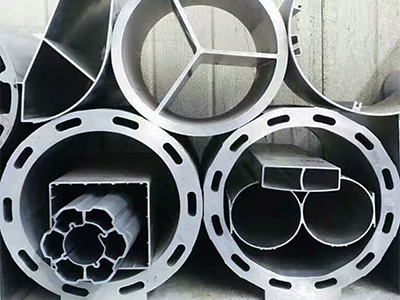
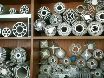
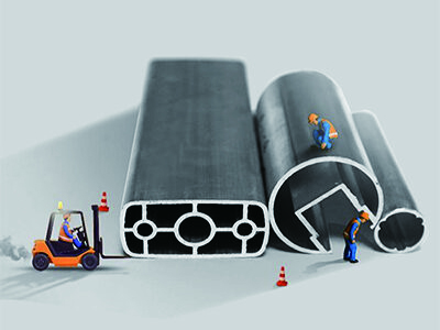
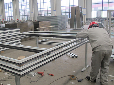
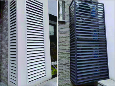
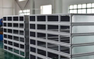
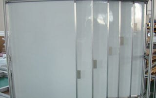
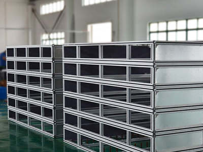
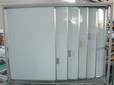
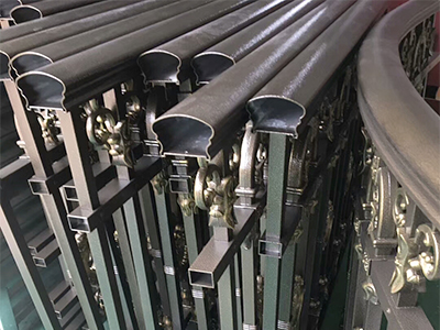
Aluminium blinds and louvres are window covering and shading systems manufactured from extruded aluminum profiles. They consist of horizontal or vertical slats (blades) that can be rotated to control light, ventilation, and privacy. It can also be applied to underground parking lots and air conditioning units.
Material Selection: Alloy & Temper Variations
The performance, cost, and manufacturability of a custom aluminum extrusion profile are fundamentally determined by the choice of alloy and temper. Among the numerous aluminum series available, the 6000 series (primarily 6061 and 6063) dominates the extrusion market, while the 7000 series serves specialized high-performance applications.
6000 Series (Al‑Mg‑Si) – The Industry Workhorse
Alloys in the 6000 series are alloyed primarily with magnesium and silicon, forming magnesium silicide (Mg₂Si) as the primary strengthening phase. They offer an excellent balance of extrudability, mechanical properties, corrosion resistance, and surface finish.
| Alloy | Key Characteristics | Typical Applications |
| Alloy 6063 | Excellent extrudability; very high surface finish quality; moderate strength (UTS ~150‑200 MPa); good anodizing response. | Architectural profiles (windows, doors, curtain walls), decorative trims, furniture, handrails, irrigation tubing. |
| Alloy 6061 | Higher mechanical strength (UTS ~240‑290 MPa); superior weldability; good corrosion resistance; slightly lower extrudability than 6063. | Heavy‑duty structural components, automotive frames, marine hardware, bicycle frames, industrial platforms, truck bodies |
Common tempers for 6000 series:
- T5 – Cooled from extrusion heat and artificially aged; typical for 6063.
- T6 – Solution heat‑treated, quenched, and artificially aged; maximum strength for both 6061 and 6063.
7000 Series (Al‑Zn‑Mg‑Cu) – High‑Strength Specialty
Alloys in the 7000 series are primarily with zinc, often with magnesium and copper additions. They deliver the highest strength‑to‑weight ratios among commercially extruded aluminum alloys. However, this performance comes with trade‑offs.
| Characteristic | Details |
| Strength | UTS can exceed 500 MPa (e.g., 7075), comparable to some mild steels |
| Extrudability | Significantly lower than 6000 series; requires slower extrusion speeds, higher pressures, and specialized die designs. |
| Corrosion Resistance | Generally lower than 6000 series; often requires protective coatings or cladding |
| Weldability | Poor to moderate; typically joined by mechanical fasteners or adhesive bonding |
| Cost | Higher raw material cost and increased processing expense |
Common alloys: 7005, 7020, 7050, 7075. (7075 is rarely extruded into complex profiles due to extreme pressure requirements).
Typical applications: Aerospace structural components (wing spars, fuselage frames), high‑performance bicycle frames, military equipment, and competitive sporting goods.
Precision Machining and Fabrication
Raw extrusions often require secondary fabrication steps before they are ready for final assembly. Precision CNC machining centers cut profiles to precise lengths, drill holes, mill slots, and tap threads. Advanced multi-axis CNC machines handle complex geometries on multiple faces of the extrusion simultaneously, ensuring tight tolerances and seamless integration with neighboring assembly parts.
Precision Machining and Fabrication
Once an extruded profile has been stretched, cut to rough length, and aged (tempered), secondary fabrication operations transform the generic extrusion into a precision component. Common processes include:
- Cutting to final length – High‑speed sawing, cold sawing, or abrasive cutting, with length tolerances often held to ±0.5 mm or tighter.
- CNC drilling and tapping – Holes for fasteners, cable pass‑throughs, or mounting points; threaded holes can be machined directly or fitted with thread‑forming inserts.
- Milling and slotting – Creating pockets, notches, keyways, or custom cutouts that cannot be formed during extrusion.
- End machining – Contouring, radius cutting, or chamfering of profile ends for aesthetic or assembly purposes.
- Deburring and edge finishing – Removing sharp edges and burrs from machined areas.
Advanced multi‑axis CNC machining centers can process several faces of an extrusion in a single setup, maintaining tight positional tolerances (typically ±0.1 mm) and ensuring that holes, slots, and mating features align perfectly with adjacent components. For high‑volume production, automated sawing and drilling lines further reduce cycle times and human error.
Anodizing, Powder Coating, and Mechanical Finishes
Surface finishing serves two primary purposes: corrosion protection and aesthetic customization. Depending on the service environment and visual requirements, one or more finishing processes may be applied.
| Finish Type | Process Overview | Key Properties | Typical Applications |
| Anodizing | Electrochemical conversion of the aluminum surface into a durable, porous aluminum oxide layer; can be sealed and dyed. | Hard, wear‑resistant, corrosion‑resistant, UV‑stable, metallic appearance; retains thermal conductivity. | Architectural glazing, consumer electronics, automotive trim, marine hardware. |
| Powder Coating | Electrostatic application of dry polymer powder followed by thermal curing (typically 180–200 °C). | Thick (60–120 µm), impact‑resistant, color‑fast, excellent UV and chemical resistance; wide color range (including textures). | Outdoor furniture, solar panel frames, industrial enclosures, handrails, fencing. |
| Mechanical Finishes | Brushing, bead blasting, sanding, or polishing to alter surface texture and remove minor die lines. | Provides a uniform matte, satin, or bright finish; improves adhesion of subsequent coatings. | Decorative profiles, pre‑anodizing preparation, architectural surfaces requiring specific grain direction. |
Additional notes:
- Anodizing can be performed in two main types: Clear (natural) anodize maintains the metallic silver appearance, while color anodizing uses organic or inorganic dyes (e.g., bronze, black, gold). Typical coating thicknesses range from 5–25 µm, with “hard anodizing” reaching 50 µm or more for extreme wear resistance.
- Powder coating is generally thicker and more forgiving of minor surface imperfections than anodizing. It also provides electrical insulation, which may be either beneficial or undesirable depending on the application (e.g., grounding requirements).
- Mechanical finishes are often applied before anodizing or powder coating to achieve a specific aesthetic (e.g., brushed satin for handrails). Bead blasting produces a uniform matte, non‑directional finish that hides extrusion lines effectively.
Frequently Asked Questions (FAQs)
These are known as die lines, which are microscopic vertical micro-scratches caused by minute imperfections or aluminum buildup on the bearing surfaces of the steel die. They can be minimized by regular die polishing, maintaining optimal nitriding schedules for the tooling, or applying post-extrusion surface finishes such as bead-blasting, brushing, or caustic etching prior to anodizing.
| Feature | General Tolerance | Precision (custom) |
| Cross‑sectional dimensions (≤50 mm) | ±0.3 – 0.5 mm | ±0.1 – 0.2 mm |
| Cross‑sectional dimensions (50–100 mm) | ±0.5 – 0.8 mm | ±0.2 – 0.4 mm |
| Wall thickness | ±10% of nominal | ±5 – 7% of nominal |
| Twist / bow | 0.3 – 1.5 mm per meter | 0.2 – 0.5 mm per meter |
| Length (cut‑to‑size) | ±1.5 – 3 mm | ±0.5 – 1 mm |
MOQs vary significantly by supplier and die complexity. For simple, small‑cross‑section profiles, MOQs may range from 300 to 500 kg (approximately 440–1,100 lbs). For larger or more complex profiles, MOQs often start at 1,000 kg (2,200 lbs) or more. Prototype quantities (as low as one full extrusion length) are possible with some suppliers using sample dies or simplified tooling, though at a higher per‑kilogram cost.
The minimum achievable wall thickness depends strongly on the specific alloy and the overall circle size of the profile. For soft alloys like 6063, wall thicknesses as thin as 0.6mm to 1.5mm can be achieved on smaller profiles. Stronger alloys like 6061 or 7075 require higher press forces, meaning they generally mandate a minimum wall thickness of 2.0mm or greater.
Custom extrusion tooling (the die) is relatively affordable compared to injection molding or stamping dies. Die costs depend on profile complexity, cross‑sectional size, and desired tool life. Typical ranges:
- Simple solid shapes (e.g., L‑angle, flat bar variants): US$120–US$800
- Moderate hollow or semi‑hollow shapes (e.g., multi‑void tubes, T‑slot): US$220–US$1,500
- Complex hollow profiles with tight tolerances: US$800–US$8,500+
Lead times for die manufacturing and initial sample production generally average between 2 to 4 weeks.
In theory, yes—but practical limitations exist. Guidelines for extrudable shapes:
- Minimum wall thickness: Typically 0.8 – 1.0 mm (0.03 – 0.04 in), though 0.5 mm is possible with specialized equipment.
- Maximum cross‑sectional width: Up to 350 – 400 mm (14 – 16 in) for most extruders; larger presses can exceed 600 mm (24 in).
- Hollow shapes: Require a hollow die (with a mandrel) and are more expensive than solid shapes.
- Sharp corners: Always require a minimum internal radius (R ≥ 0.5 mm) to avoid stress concentration and die wear.
- Asymmetric or thin‑fin profiles: May be prone to twisting and require slower extrusion speeds.
Consulting with an extrusion engineer early in the design phase is highly recommended.